Circular diffuser faces with circular plenum box
Circular diffuser faces with circular plenum box

Square diffuser face with square plenum box
Circular diffuser face with circular plenum box and top entry spigot

Horizontal swirling air discharge
Circular and square ceiling swirl diffusers that create high induction levels, for high room air change rates
■ Nominal sizes 300, 400, 500, 600, 625
■ Volume flow rate range 9 – 235 l/s or 31 – 846 m³/h
■ Diffuser face made of galvanised sheet steel, powder-coated
■ For supply and extract air
■ For variable and constant volume flows
■ For all types of ceiling systems, and with an extended border also suitable for freely suspended installation
■ High induction results in a rapid reduction of the temperature difference and airflow velocity
■ Very high room air change rate possible thanks to row arrangement with a minimum pitch distance of 0.9 m
■ Ideal for comfort zones
■ Circular diffuser faces can be easily mounted without tools in a circular plenum box with horizontal spigot
Optional equipment and accessories
■ Exposed diffuser face available in RAL CLASSIC colours
■ Square plenum box with cord-operated damper unit and pressure tap
Nominal sizes
Connection
Accessories
Lip seal
Attachments
Construction features
Standards and guidelines
Maintenance
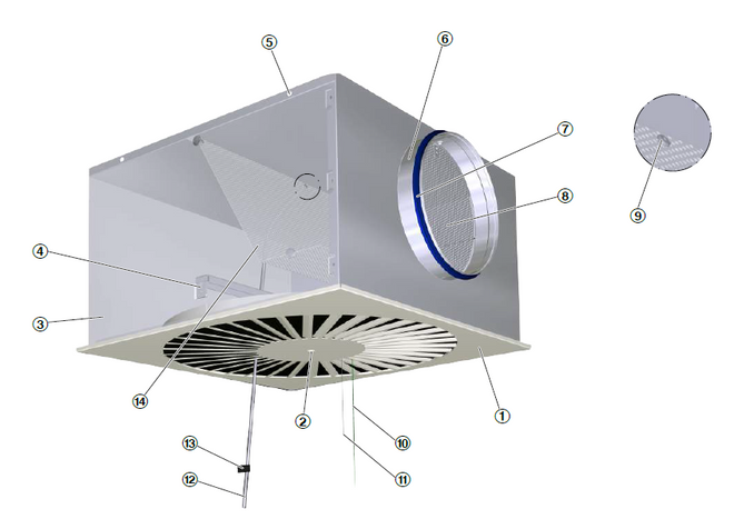
① Diffuser face ② Central fixing screw with decorative cap ③ Plenum box ④ Cross bar ⑤ Suspension hole ⑥ Spigot | Optional ⑦ Lip seal ⑧ Damper blade for volume flow rate balancing ⑨ Pressure tap ⑩ Green cord for closing the damper blade ⑪ White cord for opening the damper blade ⑫ Measuring tube ⑬ Text label indicating plenum box variant ⑭ Perforated plate as an equalising element (only for supply air) |
| Nominal sizes | 300, 400, 500, 600, 625 mm |
Minimum volume flow rate, with Δtz = -6 K | 9 – 28 l/s or 31 – 102 m³/h |
Maximum volume flow rate, with LWA ≅ 50 dB(A) | 70 – 235 l/s or 252 – 846 m³/h |
| Supply air to room air temperature difference | -12 – 10 K |
| FD | – | Q | – | Z | – | H | – | M | – | L | / | 500 | / | P1 - RAL 9016 |
| | | | | | | | | | | | | | | | | |||||||
| 1 | 2 | 3 | 4 | 5 | 6 | 7 | 8 |
1 Type
FD Swirl diffuser
2 Construction style
R circular
Q square
3 System
Z Supply air
A Extract air
4 Connection
H horizontal
V Vertical (circular plenum box)
5 Damper screen for volume flow rate balancing
No entry: without damper screen
M with damper screen
MN with cords and pressure tap (only with square plenum box)
6 Accessories
No entry: without accessories
L with lip seal
7 Nominal size [mm]
300, 400, 500, 600, 625
8 Exposed surface
No entry: powder-coated, RAL 9010 (pure white)
P1 powder-coated, specify RAL CLASSIC colour
Gloss level
RAL 9010 GU 50
RAL 9006 GU 30
All other RAL colours GU 70
Note: Circular plenum boxes with a horizontal spigot have either no damper blade and no lip seal or both a damper blade and a lip seal. Items 2 and 4 define apply to the plenum box.
Order example: FD–Q–Z–H–MN/500/P1–RAL 9016
| Construction style | Square |
| System | Supply air |
| Connection | Horizontal |
| Damper blade for volume flow rate balancing | With cord and pressure tap |
| Accessories | without accessories |
| Nominal size | 500 |
| Exposed surface | RAL 9016, traffic white, GU70 |
Споделете страницата
Препоръчайте тази страница
Препоръчайте тази страница чрез изпращане на линк по имейл.
Споделете страницата
Благодарим Ви за Вашата препоръка!
Вашата препоръка е била изпратена и трябва да пристигне в кратък срок.
За контакти
Ние сме тук за Вас

Моля, уточнете съобщението си и типа на искането
Тел.: +359 2 981 25 74 | Факс: +359 2 986 20 65
За контакти
Благодарим Ви за Вашето съобщение!
Вашето съобщение е изпратено и ще бъде обработено в кратък срок.
Нашият отдел за Обслужване-Искания ще се свърже с Вас възможно най-скоро.
За общи въпроси относно продукти или услуги можете да се свържете също с:
Тел.: +359 2 981 25 74 | Факс: +359 2 986 20 65
За контакти
Ние сме тук за Вас
Моля, уточнете съобщението си и типа на искането
Тел.: +359 2 981 25 74 | Факс: +359 2 986 20 65
За контакти
Благодарим Ви за Вашето съобщение!
Вашето съобщение е изпратено и ще бъде обработено в кратък срок.
Нашият отдел за Обслужване-Искания ще се свърже с Вас възможно най-скоро.
За общи въпроси относно продукти или услуги можете да се свържете също с:
Тел.: +359 2 981 25 74 | Факс: +359 2 986 20 65


